
Converting 2-Wire Signals to 3-Wire Functionality
This is a How-to on producing the same functionality that the front stock turn signals had, but with your new 2-wire aftermarket signals.
Here are the final Results:
The turn signal light on the Left of your screen is the Relay Option
The turn signal on the Right is utilizing the Diode/Resistor Option
This mod comes in two flavors:
1. Relay Option – This keeps your running light at full brightness and the light blinks on/off when the turn indicator is activated.
2. Diode/Resistor Option – This keeps the signal dimly lit, flashing at full brightness when the turn indicator is activated.
What you will need:
Soldering iron, resin core solder and flux. Electrical Tape. Wire Cutter/Strippers. 30 minutes.
Relay Option:
http://www.radioshack.com/product/index.jsp?productId=2062481&CAWELAID=107591283 (12V, 1A Relay)
Diode/Resistor Option:
http://www.radioshack.com/product/index.jsp?productId=2062589 (1N4001 Rectifying Diode)
http://www.radioshack.com/product/index.jsp?productId=2062342 (470Ω Resistors)
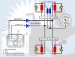
Electrical Schematic of Relay Option & Diode/Resistor Option :
![Image]()
Electrical Schematic of relay:
![Image]()
Step 1: Cut 3 wire OEM turn signal lead, NOT THE HARNESS!!
![Image]()
Step 2: Cut the 2 wire aftermarket turn signal lead.
![Image]()
Step 3: Prep the wires
![Image]()
Step 4: Wire according to the schematic
Final Result of wiring on Relay Option: Note both grounds (black) are soldered on the same post. Also one on the relay posts is left floating.
![Image]()
Final result of wiring on Diode/Resistor Option: (Solder these first, you can twist together prior to soldering if needed)
![Image]()
![Image]()
Step 5: Insulate the exposed metal surfaces with electrical tape
I personally decided on going the Diode/Resistor Option but kept the relays in case I want to change it.
:cheers Enjoy :cheers
This is a How-to on producing the same functionality that the front stock turn signals had, but with your new 2-wire aftermarket signals.
Here are the final Results:
The turn signal on the Right is utilizing the Diode/Resistor Option
This mod comes in two flavors:
1. Relay Option – This keeps your running light at full brightness and the light blinks on/off when the turn indicator is activated.
2. Diode/Resistor Option – This keeps the signal dimly lit, flashing at full brightness when the turn indicator is activated.
What you will need:
Soldering iron, resin core solder and flux. Electrical Tape. Wire Cutter/Strippers. 30 minutes.
Relay Option:
http://www.radioshack.com/product/index.jsp?productId=2062481&CAWELAID=107591283 (12V, 1A Relay)
Diode/Resistor Option:
http://www.radioshack.com/product/index.jsp?productId=2062589 (1N4001 Rectifying Diode)
http://www.radioshack.com/product/index.jsp?productId=2062342 (470Ω Resistors)
Electrical Schematic of Relay Option & Diode/Resistor Option :

Electrical Schematic of relay:

Step 1: Cut 3 wire OEM turn signal lead, NOT THE HARNESS!!

Step 2: Cut the 2 wire aftermarket turn signal lead.

Step 3: Prep the wires

Step 4: Wire according to the schematic
Final Result of wiring on Relay Option: Note both grounds (black) are soldered on the same post. Also one on the relay posts is left floating.

Final result of wiring on Diode/Resistor Option: (Solder these first, you can twist together prior to soldering if needed)


Step 5: Insulate the exposed metal surfaces with electrical tape
I personally decided on going the Diode/Resistor Option but kept the relays in case I want to change it.
:cheers Enjoy :cheers
")